Introduction of Inverter Technology
In the grid-interconnected photovoltaic power system, the DC output power of the photovoltaic array should be converted into the AC power of the utility power system. Under this condition an inverter to convert DC power into AC power is required. Apart from the solar panels, the core technology associated with these systems is a power-conditioning unit (inverter) that converts the solar output electrically compatible with the utility grid.
Most inverters in the mid 1990 have consisted of a central inverter of dc power rating above 1 kW. They connect several solar panel strings in parallel via a dc bus. However, the concept has the drawbacks of causing a complete loss of generation during inverter outage and losses due to the mismatch of strings . Later, string inverters, which are designed for a system of one string of panels, were used to lessen the problems and have become popular nowadays. With further system decentralization, concept of “AC-module” was introduced. Every solar panel has a module-integrated inverter of power rating below 500 W mounted on the backside [80]–84]. This panel inverter integration allows a direct connection to the grid and provides the highest system flexibility and expandability. It also offers the possibilities to overcome problems with respect to high dc voltage level connection, safety, cable losses, and risk of dc arcs, and to achieve high-energy yield in case of system suffering from shading effect, due to the lack of mutual influence among modules’ operating points .Typical structures of the AC-module consist of several power conversion stages (Fig. 1) .
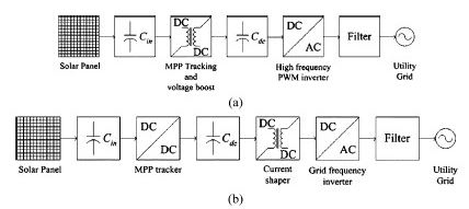
Figure (37): Typical structures of grid-connected PV systems. (a).with voltage-fed
self-commutated inverter switching at high frequency.
(b) current-fed, grid- commutated inverter switching at the grid frequency.
The line commutated inverter uses a switching device like a commutating thyristor that can control the timing of turn-on while it cannot control the timing of turn-off by itself. Turn-off should be performed by reducing circuit current to zero with the help of supplemental circuit or source. Conversely, the self-commutated inverter is characterized in that it uses an switching device that can freely control the ON-state and the OFF-state, such as IGBT and MOSFET. The self-commutated inverter can freely control the voltage and current waveform at the AC side, and adjust the power factor and suppress the harmonic current, and is highly resistant to utility system disturbance. Due to advances in switching devices, most inverters for distributed power sources such as photovoltaic power generation now employ a self-commutated inverter. The front stage has a maximum power point (MPP) tracker for maximizing the output power of the panel, because the maximum power drawn from the panel varies with temperature and insolation. The grid-connected stage uses a full-bridge inverter toward the grid, either self-commutated with a high switching frequency [Fig. 37(a)],
or grid-commutated at the grid frequency [Fig. 37(b)]. In the former structure [Fig. 37(a)], the panel voltage is firstly boosted to the grid level together with the tracker. The dc/ac conversion stage, which is usually a pulse-width-modulated (PWM) voltage-source inverter, shapes and inverts the output current. A high-frequency filter is used to eliminate the high-frequency component at the inverter output. In the latter structure [Fig. 37(b)], the tracker, voltage boost, and output current shaping are performed in the front stage. The full bridge is switched at the grid frequency for inverting the shaped output current [85]. There are various types of inverters as shown in Fig. 2.
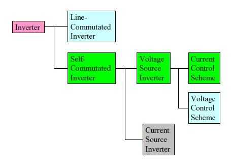
Figure (38): classification of inverter type
The Self-commutated inverters include voltage and current types. The voltage type is a system in which the DC side is a voltage source and the voltage waveform of the constant amplitude and variable width can be obtained at the AC side. The current type is a system in which the DC side is the current source and the current waveform of the constant amplitude and variable width can be obtained at the AC side. In the case of photovoltaic power generation, the DC output of the photovoltaic array is the voltage source, thus, a voltage type inverter is employed. The voltage type inverter can be operated as both the voltage source and the current source when viewed from the AC side, only by changing the control scheme of the inverter.
When control is performed as the voltage source (the voltage control scheme),the voltage value to be output is applied as a reference value, and control is performed to obtain the voltage wave form corresponding to the reference value. PWM control is used for waveform control. This system determines switching timing by comparing the waveform of the sinusoidal wave to be output with the triangular waveform of the high-frequency wave,
leading to a pulse row of a constant amplitude and a different width. In this system, a waveform having less lower-order harmonic components can be obtained. On the other hand,
when control is performed as the current source (the current control scheme), the instantaneous waveform of the current to be output is applied as the reference value. The switching device is turned on/turned off to change the output voltage so that the actual output current agrees with the current reference value within certain tolerance. Although the output voltage waveforms of the voltage control scheme and the current control scheme look substantially same, their characteristics are different because the object to be controlled is different. Table 1.2 shows the difference between the voltage control scheme and the current control scheme. In a case of the isolated power source without any grid interconnection, voltage control scheme should be provided. However, both voltage-control and current-control schemes can be used for the grid interconnection inverter. The current-controlled scheme inverter is extensively used for the inverter of a grid interconnection photovoltaic power system because a high power factor can be obtained by a simple control circuit, and transient current suppression is possible when any disturbances such as voltage changes occur in the utility power system. Fig. 1.2 shows the configuration example of the control circuit of the voltage-type current-control scheme inverter.
|
Voltage control scheme |
Current control scheme |
|
|
Inverter main circuit |
Self-commutated voltage source inverter (DC voltage source) |
|
|
Control objective |
AC voltage |
AC current |
|
Fault short circuit current |
High |
Low (Limited to rated current) |
|
Stand alone operation |
Possible |
Not possible |
Table: Difference between the voltage control scheme and the current control scheme inverter
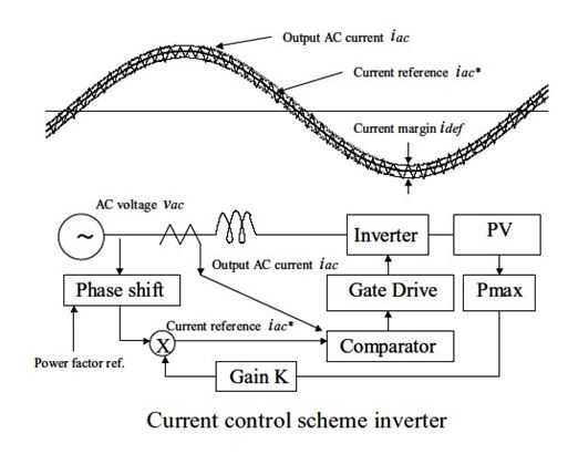
Figure (39): configuration example of the control circuit of the voltage-type current-control
Scheme inverter
Types of inverter
There are various types of inverter system configuration. However, Self-commutated inverter is usually used in a system with a relatively small capacity of several kW, such as a photovoltaic power system. This situation is reflected well by the results of this survey. The results of the survey show that the self-commutated voltage type inverter is employed in all inverters with a capacity of 1 kW or under, and up to 100 kW. The output waveform is adjusted by PWM control, which is capable of obtaining the output with fewer harmonic. The current control scheme is mainly used as described in Fig.39. However, some inverters employ the voltage control scheme. The current control scheme is employed more popularly because a high power factor can be obtained with simple control circuits, and transient current suppression is possible when disturbances such as voltage changes occurs in the utility power system. In the current control scheme, operation as an isolated power source is difficult but there are no problems with grid interconnection operation.
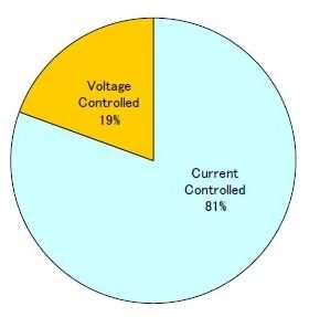
Figure (40): Ratio of current controlled scheme and voltage controlled Scheme inverter.
Switching Devices:
To effectively perform PWM control for the inverter, high frequency switching by the Semiconductor-switching device is essential. Due to advances in the manufacturing technology of semiconductor elements, these high-speed switching devices can now be used. Insulated Gate Bipolar Transistor (IGBT) and Metal Oxide Semiconductor Field Effect Transistor (MOSFET) are mainly used for switching devices. IGBT is used in 62% of the surveyed products, and MOSFET is used in the remaining 38%. Regarding differences in characteristics between GBT and MOSFET, the switching frequency of IGBT is around 20 kHz; IGBT can be used even for large power capacity inverters of exceeding 100 kW, while the switching frequency of MOSFET is possible up to 800 kHz, but the power capacity is reduced at higher frequencies. In the output power range between 1 kW to 10 kW, the switching frequency is 20 kHz, thus, both IGBT and MOSFET can be used. High frequency switching can reduce harmonics in output current, size, and weight of an inverter.
PWM inverter use for grid connection usually operates in the current source .while voltage and frequency determined by the grid, they inject a maximum current into d grid, depending on the DC power available. The power factor of the inverter bridge usually is set to unity [56].
A control algorithm is implemented in order to adapt the inverter’s operating point to variations in the I-U curve of the PV array, due to the temperature of irradiance variations. This so called MPP tracker continuously checks weather the inverter is operating at the arrays MPP and if necessary, adjust the inverter’s output current.

Figure (41): basic scheme of a PWM inverter with low frequency transformer for PV grid connection.
2.3 Operational Conditions
2.3.1 Operational AC voltage and frequency range
Inverter should be operated without problem for normal fluctuations of voltage and frequency at the utility grid side. Accordingly, the operable range of the inverter is determined according to the conditions at the AC utility grid side. Because the conditions of the distribution system for interconnection differ by country, the operable range of the inverter also differs by country. The standard voltage and frequency for a single phase circuit is 230V and 50 Hz in Europe, 101/202 V and 50/60 Hz in Japan, and 120/240V and 60 Hz in USA. The standard voltage and frequency for a three-phase circuit is 380/400V and 50 Hz in Europe, 202 V and 50/60 Hz in Japan, and 480V and 60 Hz in the USA. For these standard values, the inverter can be operated substantially without any problems within the tolerance of +10% and –15% for the voltage, and ±0.4 to 1% for the frequency.
2.3.2 Operational DC voltage range
On the other hand, the operable range of the DC voltage differs according to rated power of the inverter, rated voltage of the AC utility grid system, and design policy, and various values are employed. In this survey, the operable range of the DC voltage for a capacity of 1 kW or below includes 14-25V, 27-50V, 45-100V, 48-120V, and 55-110V. In addition, the operable DC voltage range for a capacity of 1 kW to 10 kW includes 40-95V, 72-145V, 75-225V, 100-350V, 125-375V, 139-400V, 150-500V, 250-600V, and 350-750V. The operable DC voltage range for a capacity of10 kW or over includes 200-500V, and 450-800V.
Applicable PV array power
Fig. 45 shows the results of the survey for applicable rated power of the PV array to the rated output power of inverter. Although it cannot be defined unconditionally because the array output power differs according to conditions (latitude, angle of inclination of module, etc.) in an area in which the photovoltaic power system is installed, the PV array of the rated output power of about1.3 times the rated output power of the inverter can be applied on average.
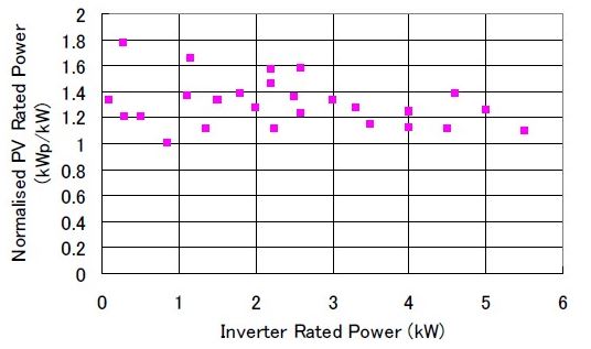
Figure (42): PV rated power distribution
AC harmonic current from inverter
For the characteristic of the inverter, minimization of harmonic current production is required. As described in the Report of Task 5 “Utility Aspects of Grid Interconnected PV systems,” Report IEA-PVPS T5-01: 1998, December 1998, harmonic current adversely affects load appliances connected to the distribution system, and can impair load appliances when the harmonic current is increased. As described in Chapter 2, because the PWM control scheme is employed as the output waveform control of the inverter, the harmonic current from the inverter is very small, raising fewer problems. The results of this survey show that Total Harmonic Distortion (THD), the total distortion factor of the current normalized by the rated fundamental current of the inverter, is 3 to 5%.
3.1 Inverter System Cost:
The cost of the inverter system is an important element when considering the economy of a Photovoltaic power system. Here, the cost of the inverter system including the control device and the protective device is summarized. The cost of the inverter system was also summarized in the survey of 1998. According to the results of the previous survey, the difference in the cost was large by country and manufacturer, even when the power capacity of the inverter system was the same, and the cost varied greatly. However, the cost is substantially stabilized in this revised survey. Fig. 3.6 shows the results of the cost survey in the previous survey (old survey) and the revised survey (new survey) at the same time. Cost is indicated in USD when survey replies were in the currency of each country. The currency exchange rate was based on the values in 2001; 1German Mark was 0.46 US dollar, 1 Yen was 0.0075 USD, and 1 Euro was 1.07 USD.
As a result, it is shown that the cost of the inverter system is reduced more in the present survey than in the previous survey on the whole, and the cost for 1 kW is 800 USD or less in the present survey. It is also shown that the cost per kW decreases as inverter power capacity increases. Differences by country and manufacturer are also reduced, and the cost level becomes similar worldwide. It is expected that the cost of the inverter system will be further reduced. Fig. 5.1 shows a summary of the inverter system cost with a capacity from 1 kW to 6 kW. The cost of the inverter for the AC module with a capacity as low as 100 W to 300 W was 1 USD/W in the previous survey, while it is 1.2 to 1.9 USD/W in the present survey, showing that the cost has slightly increased. In addition, for the system with a large capacity exceeding 10 kW, cost per kW is apt to be reduced when capacity is increased. However, this cannot be concluded uniquely because cost depends on the number of production, and cost per kW increases if the number manufactured is small.
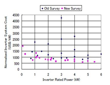
Figure (43): Inverter system cost
In early 1990s PV inverter were only produce in small series. Every single device were assembled manually often by the small inverter enterprises. in practice this led to a high failure rate and often a long repair time [85] .currently an increasing professionalism can be identified. Failure rate and repair time of inverter have been reduced considerably [85].
Especially the larger production facilities have been semi-automated.
In future more and more pre-assembled component will be applied [86].Manufacturers of power-electronic components offer assembly group of IGBTs for chopper module, half-bridge and three-phase bridge. The application of such preassembled group is another step of further increase reliability and decreases the production costs of photovoltaic inverters. [86]
Inverter Efficiency:
Modern PV inverter has conversion efficiency from DC to AC of more than 90% over a wide power range including low partial load. In a PV inverter three types of losses occur:
– Open-circuit losses, constant;
– Voltage-drop losses, current-proportional;
– Resistance losses ,proportional to the current square [88];
–
Assuming approximately constant voltage, the inverter current is proportional to the DC power. In that case the losses as a function of DC power PDC may be approximated by a second order polynomial [89]:
![]()
Where PDC and PL are dc power and losses, respectively, normalized to rated DC power PDC,
The polynomial coefficients and can be determined from measured data by least square fitting.
The inverter efficiency is

With PL from (1) ,the normalized losses as a function of PDC.
If the available PV power at the MPP exceeds the rated DC power, the inverter limits the input power to power PDC, r. The efficiency of a PV inverter limits the input power to PDC.
The efficiency of a PV inverter based on measurement and second-order polynomial approximation is given in figure….. The decrease in efficiency due to the current limiting is visible for PDC.

Figure (44): Inverter efficiency as a function of normalized DC power inverter
From field measurement and polynomial curve fitting;
![]()
The efficiency is not always constant over the full power range. In order to characterize the long-time efficiency of photovoltaic inverter in the field, the European efficiency η Eu has been introduced:
![]()
Where the subscripts indicates the efficiency at operating points, weights according to their frequency of occurrence under typical European climate conditions.
Conclusions:
PV grid interconnection inverters have fairly good performance. They have high conversion efficiency and a power factor exceeding 90% over a wide operational range, while maintaining current harmonics THD less than 5%. Cost, size, and weight of a PV inverter have been reduced recently, because of technical improvements and advances in the circuit design of inverters and integration of required control and protection functions into the inverter control circuit. The control circuit also provides sufficient control and protection functions such as maximum power tracking, inverter current control, and power factor control. There are still some subjects as yet unproven. Reliability, life span, and maintenance needs should be certified through long-term operation of a PV system. Further reductions of cost, size, and weight are required for the diffusion of PV systems.
