Electricity is an influential instrument, and it is all over the place. Electrical contractors are conscious of the dangers connected with cabling and preservation, and building owners should be knowledgeable, as fine. At a least, most citizens should appreciate what to do during the event of an electrical disaster.
EEE
Primary objective of this lecture is to analysis Discrete Mathematics and its Applications based on Trees. A tree is often a connected undirected graph without any simple circuits. Brief hypothesis: An undirected graph is often a tree if and only if there is a unique simple way between any two associated with its vertices. Here briefly explain Internal Vertex and Binary Tree. Here also analysis on Ancestors: The ancestors of a non-root vertex are all the vertices in the path from root to this vertex and Descendants: The descendants of vertex v are all the vertices that have v as an ancestor. Finally discuss Traversal Algorithms with examples.
This lecture focus to explain Bottleneck Node Avoidance Data Gathering Tree forWireless Sensor Networks. Here briefly explain Wireless Sensor Network (WSNs), Energy Problem in WSNs, Data Gathering Methodology and Data Gathering Tree (DG), Energy Aware Maximum Leaf node DG (EML-DG), Proposed Energy Aware Bottleneck Avoidance Shortest Path DG etc. Finally discuss on some advantages of Wireless Sensor Networks, like: decrease the total energy lost per round, decrease path cost, increase average lifetime of the bottlenecks, decrease height of the tree and increase the lifetime of the network.
Transformer Tests
The performance of a transformer can be calculated on the basis of equivalent circuit which contains four parameters, the equivalent resistance R01 as referred to primary (or secondary R02), the equivalent leakage reactance X01 as referred to primary (or reactance in secondary X02), the core loss conductance G0 (or resistance R0) and the magnetizing susceptance B0 (or reactance X0).
These constants or parameters can be easily determined by two tests
(i) open-circuit test and
(ii) short-circuit test
Open-Circuit or No-Load Test
The purpose of this test is to determine no-load loss or core loss and no-load current I0 which is helpful in finding X0 and R0.
Low voltage side connected with normal voltage and frequency and high voltage side is left open.
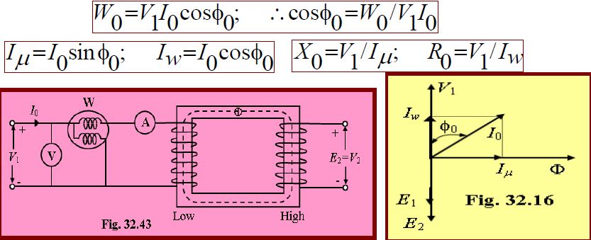
A wattmeter W, voltmeter V and an ammeter A are connected in the low-voltage winding i.e. primary winding in the present case as shown in Fig. 32.43.
The voltage V1 is measured using the voltmeter (V). With normal voltage applied to the primary, normal flux will be set up in the core, hence normal iron losses will occur which are recorded by the wattmeter (W).
As the primary no-load current I0 (as measured by ammeter, A) is small, Cu loss is negligibly small in primary and null in secondary. Hence, the wattmeter reading represents practically the core loss under no-load condition (and which is the same for all loads). The no-load vector diagram is shown in Fig. 32.16. If W0 is the wattmeter reading as shown in Fig. 32.43, then
Since the current is practically all-exciting current when a transformer is on no-load (i.e. I0=I) and as the voltage drop in primary leakage impedance is small, hence the exciting admittance Y0(=1/Z0) of the transformer is given by I0=V1Y0 or Y0=I0/V1.
The exciting conductance G0 is given by W0=V12G0 or G0(=1/R0)= W0 /V12.
Separation of Core Losses
The core loss of transformer depends upon the frequency and the maximum flux density when the volume and the thickness of the core lamination are given.
The core loss is made up of two parts:
(i) Hysteresis loss: Wh=PBmax2f and
(ii) Eddy current loss: We=QBmax2f 2
Where, P and Q are constant.
The total core loss is given by: Wi=Wh+We= PBmax2f + QBmax2f 2.
If we carry out two experiments using two different frequencies but the same maximum flux density, we should be able to find the constants P and Q and hence calculate hysteresis and eddy current losses separately.
If the maximum flux can be kept same value then the iron or core losses can be written as follows:
Wi=Wh+We= Af +Bf 2; where, A= PBmax2; B= QBmax2.
From the measured the core loss in two different frequencies, the constant A and B can be calculated.
Example 32.31 In a test for determination of losses of a 440 V, 50 Hz transformer, the total iron losses were found 2500 W at normal voltage and frequency. When the applied voltage and frequency 220 V and 25 Hz, the iron losses were found 850 W. Calculate the eddy-current loss and hysteresis loss at normal voltage and frequency. [Ans:We = 1600WandWh = 900 W]
Short-Circuit or Impedance Test
This is an economical method for determining the following:
(i) Equivalent impedance (Z01 or Z02), leakage reactance (X01 or X02) and total resistance (R01 or R02) of the transformer as referred to the winding in which the measuring instruments are placed.
(ii) Cu loss at full load. This loss is used in calculating the efficiency of the transformer.
(iii) Knowing Z01 or Z02, the total voltage drop in the transformer as referred to primary or secondary can be calculated and hence regulation of the transformer determined.
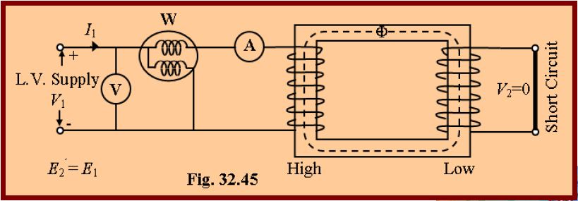
In this test, one winding, usually the low-voltage winding is solidly short-circuited by a thick conductor as shown in Fig. 32.45.
A low-voltage (usually 5 to 10% of normal primary voltage) at correct frequency is applied to the primary and is cautiously increased till full-load currents are flowing both in primary and secondary (as indicated by the respective ammeters).
Since the applied voltage is a small percentage of the normal voltage, the mutual flux F produced is also a small percentage of its normal value.
Hence, core losses are very small with the result that the wattmeter reading represents the full-load Cu loss or I2R loss for the whole transformer i.e. both primary Cu loss and secondary Cu loss.
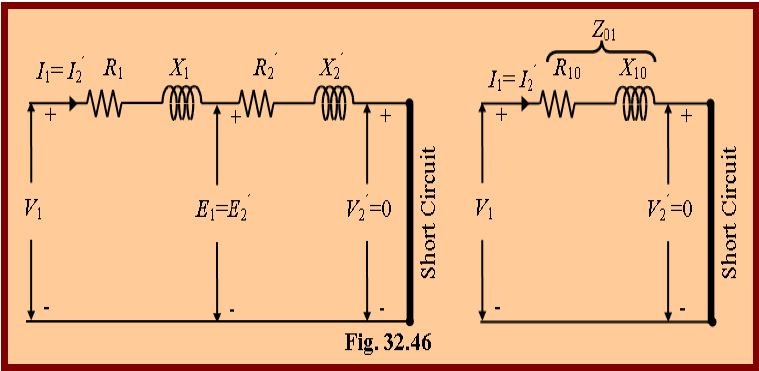
The equivalent circuit of the transformer under short circuit condition is shown in Fig. 32.46.
If VSC is the voltage required to circulate rated load currents.
Then Z01=VSC/I1. Also W=I12R01. \ R01=W/I12 and ![]()
If R1 and X1 can be measured, then knowing R01 and
X01, we can find R2’=R01-R1 and X2’=X01-X1.
Hence, the secondary resistance and reactance can be calculated by using the following equation: R2= R2’K2;
X2= X2’K2 .
Example 32.36 Obtain the equivalent circuit of a 200/400 V, 50 Hz, 1-phase transformer from the following data:
O.C (Open Circuit) test: 200V, 0.7A, 70W on l. v (low voltage) side
S.C (Short Circuit) test: 15V, 10A, 85W on h. v (high voltage) side
Calculate the secondary voltage when delivering 5kW at 0.8 pf (power factor) lagging, the primary voltage being 200V.
Solution: From O.C Test: V1I0cosf0=W0.200×0.7×cosf0=70.
cosf0=70/(200×0.7)=0.5 and sinf0=0.866.
Iw=I0cosf0= 0.7×0.5=0.35 A. Im=I0sinf0=0.7×0.866=0.606 A.
R0=V1/Iw=200/0.35=571.4W. X0=V1/Im=200/0.606=330W.
From S.C Test: It may be noted that in this test, instruments have been placed in the secondary i.e high-voltage winding whereas the low voltage side i.e primary has been short circuited. Where K=400/200=2;
Z02=VSC/I2=15/10=1.5W. Z01=Z02/K2=1.5/4=0.375W.
Also, I22R02=W; R02=85/100=0.85 W. R01=R02/K2=0.85/4=0.21 W.
The equivalent circuit is shown in Fig. 32.49.
The values of parameters are referred to primary i.e. low voltage side.
Output kVA=5/0.8=6.25; Output current, I2=6.25×1000/400=15.6 A
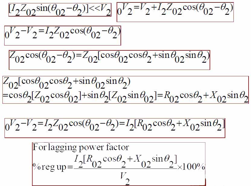
Total transformer drop as referred to secondary
=I2(R02cosf2+X02sinf2)
=15.6× (0.85×0.8+1.24×0.6)=22.2 V
V2= 400-22.2=377.8 V
Why Transformer Rating in kVA?
As seen, Cu loss of transformer depends on current and iron loss on voltage.
Hence, total transformer loss depends on volt-ampere (VA) and not on phase angle between voltage and current i.e. it is independent of load power factor.
This is why rating of transformers is in kVA and not in kW.
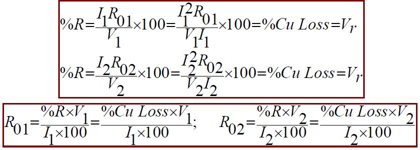
Percentage Resistance [%R]
Percentage resistance is the resistance drop in volts at rated current and frequency as a percentage of the rated voltage i.e. [if I is rated current, V is rated voltage then]
Percentage Reactance [%X]
Percentage reactance is the reactance drop in volts at rated current and frequency as a percentage of the rated voltage i.e. [if I is rated current, V is rated voltage then]
Percentage Impedance [%Z]
Percentage impedance is the impedance drop in volts at rated current and frequency as a percentage of the rated voltage i.e. [if I is rated current, V is rated voltage then]
Percentage Resistance of Transformer at Full-Load
Percentage Reactance of Transformer at Full-Load
Percentage Impedance of Transformer at Full-Load
The advantage of expressing resistance and reactance of a transformer in percentage is that the percentage resistance and reactance have the same values whether determined referred to primary or secondary whereas when expressed in ohms they have different values when referred to the primary and secondary.
Per Unit Values
The per unit values are equal to the percentage values divided by 100.
Regulation of a Transformer Or Transformer Regulation
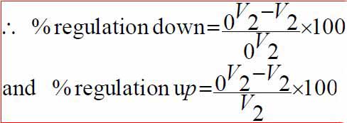
Regulation of a transformer is defined as the difference between the full-load and no-load secondary terminal voltages expressed as a percentage of the full-load voltage.
When a transformer is loaded with a constant primary voltage, the secondary voltage decreases because of its internal resistance and leakage reactance.
Let, 0V2 = secondary terminal voltage at no-load = E2 = E1K=KV1 because at no-load the impedance drop is negligible.
V2 = secondary terminal voltage on full load
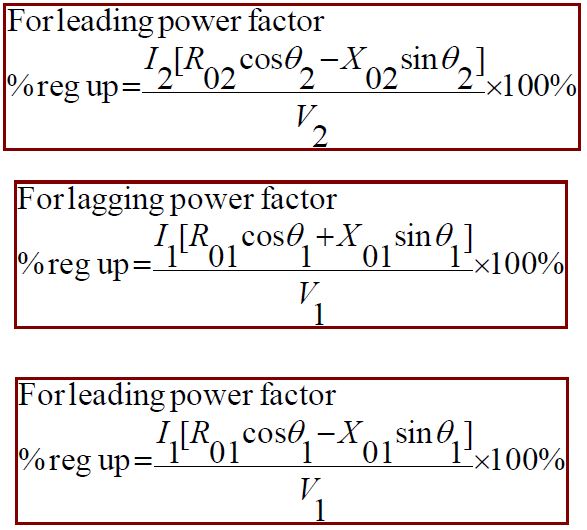
The change in secondary terminal voltage from no-load to full load is=0V2-V2.
This change divided by 0V2 is known as regulation ‘down’.
If this change is divided by V2 i.e. full-load secondary terminal voltage, then it is called regulation ‘up’.
Regulation is usually to be taken as regulation ‘down’.
The lesser this value, the better the transformer, because a good transformer should be kept secondary terminal voltage as constant as possible under all conditions of load.
Losses in Transformer
Since a transformer is a static device, there are no friction and windage losses.
Hence, the only losses occurring are:
(a) Core or Iron Loss
(b) Copper Loss
Core or Iron Loss
It includes both hysteresis loss and eddy current loss.
Because the core flux in transformer remains practically constant for all loads the core loss is practically the same at all loads.
Hysteresis loss: Wh=hBmax1.6fV watt; Eddy current loss: We=PBmax2f 2t2 watt
Where, V=volume of the core in m3; h=Steinmetz hysteresis coefficient;
t=thikness.
These losses are minimized by using steel of high silicon content for the core and by using very thin laminations.
Iron or core loss is found from the O.C. test.
The input of the transformer when on no-load measures the core loss.
Copper Loss
This loss is due to the ohmic resistance of the transformer windings.
Total Cu loss=I12R1+I22R2= I12R01=I22R02.
It is clear that Cu loss is proportional to (current)2 or kVA2.
So, Cu loss at half-load is one-fourth [(1/2)2=1/4] of that at full load.
Cu loss at one-quarter-load is one-sixteen [(1/4)2=1/16] of that at full load.
Cu loss at five-fourths -load is twenty five by-sixteen [(5/4)2=25/16] of that at full load.
The value of copper loss is found from the short-circuit test.
Auto Transformer
The transformer with one winding only, part of this being common to both primary and secondary, is called auto transformer.
In this transformer the primary and secondary are not electrically isolated from each other as is the case with a 2-winding transformer.
But its theory and operation are similar to those of a two winding transformer.
Because of one winding, it uses less copper and hence is cheaper.
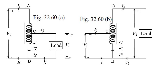
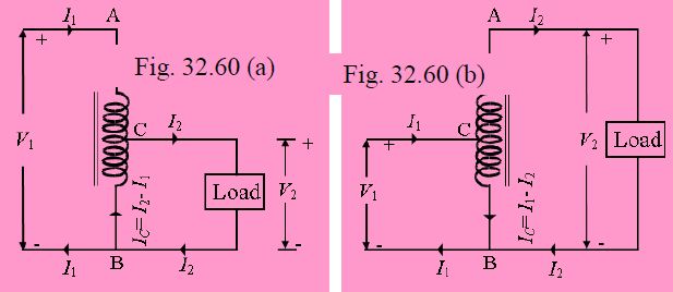
Fig. 32.60 shows both step-down and step-up auto- transformer.
As shown in Fig. 32.60(a), AB is primary winding having N1 turns and BC is secondary winding having N2 turns.
Neglecting iron losses and no-load current: ![]()
The current in section CB is vector difference of I2 and I1.
But as the two currents are practically in phase opposition, the resultant current is (I2-I1) where I2 is greater than I1.
As compared to an ordinary 2-winding transformer of same output, an auto transformer has higher efficiency but smaller size.
Moreover, its voltage regulation is also superior.
Merits of an Auto-Transformer Over a Two-Winding Transformer
(i) Smaller in size, (ii) Lower cost, (iii) Better efficiency, (iv) Less exciting current, and (v) Better voltage regulation.
Demerits of an Auto-Transformer Over a Two-Winding Transformer
(i) No electrical isolation. There is a direct connection between the HV and LV sides. (ii) Should an open circuit occur in common part the fully primary voltage would be applied to the load on the secondary side causing series damage if K<<1. (iii) The short circuit current is larger than that for the two-winding transformer.
Saving of Copper
Volume and hence weight of Cu, is proportional to the length and area of cross section of the conductors.
Length of conductor is proportional to the number of turns and cross section depends on current.
Hence, weight is proportional to the product of the current and number of turns.
With reference to Fig. 32.60
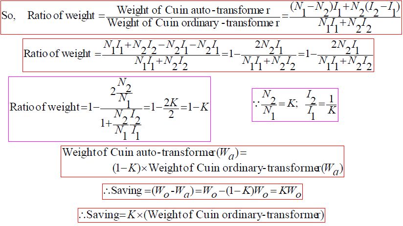
Weight of Cu in section AC(N1- N2)I1;
Weight of Cu in section BC(I2- I1)N2;
So, total weight of Cu in auto-transformer (Wa) (N1- N2)I1+(I2- I1)N2;
If a two winding transformer were to perform the same duty, then
Weight of Cu in primaryN1I1;
Weight of Cu in secondaryN2I2;
Total weight of Cu (Wo) N1I1+N2I2;
Hence, saving will increase as K approaches unity.
It can be proved that power transform inductively is= input(1-K)
The rest of the power= (K x input) is conducted directly from the source to the load i.e. it is transferred conductively to the load.
Uses of Auto Transformer
Auto transformers are used:
1. To give small boost to a distribution cable for the voltage drop.
2. As auto-starter transformers to give up to 50 to 60% of full voltage to an induction motor during starting.
3. As furnace transformers for getting a convenient supply to suit the furnace winding from a 230 V supply.
4. As interconnecting transformer in 132 kV/330 kV system.
5. In control equipment for 1-phase and 3-phase electrical locomotives.
Conversion of 2-winding Transformer into Auto-Transformer
Any two-winding transformer can be converted into an auto transformer either step-down or step-up. Fig. 32.62(a) shows such a transformer with its polarity marking.
If we employ additive polarity between the high-voltage and low voltage sides, we get a step-up transformer.
If, however, we use the subtractive polarity, we get a step-down auto-transformer.
Additive Polarity
Connections for such a polarity are shown in Fig. 32.62(b).
The circuit is re-drawn in Fig. 32.62(c) showing common terminal at the bottom.
Because of additive polarity, V2=2400+240=2640 V and V1 is 2400 V.
As shown in Fig. 32.62(d), common current flows towards the common terminal. The transformer acts as a step-up transformer.
Subtracting Polarity
Such a connection is shown in Fig. 32.63(a).
The circuit has been re-drawn with common polarity at top in Fig. 32.63(b) and in Fig. 32.63(c).
In this case, the transformer acts as a step-down auto-transformer.
The common current flows away from the common terminal.
Here V2= 2400-240= 2160 V.
Parallel Operation of Single Phase Transformer
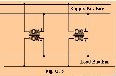
For supplying a load in excess of the rating of an existing transformer, a second transformer may be connected in parallel with it as shown in Fig. 32.75.
The primary windings are connected to the supply bus bars and secondary winding are connected to the load bus-bars.
In connecting two or more than two transformers in parallel, it is essential that their terminals of similar polarities are joined to the same
bus bars.
If this is not done, the two emfs induced in the secondaries which are paralleled with incorrect polarities, will act together in the local secondary circuit even when supplying no load and will hence produce the equivalent of a dead short-circuit.
There are certain definite conditions which must be satisfied in order to avoid any local circulating currents and to ensure that the transformers
share the common load in proportion to their kVA ratings.
The conditions are:
1. Primary winding of the transformers should be suitable for the supply system voltage and frequency.
2. The transformer should be properly connected with regard to polarity.
3. The voltage ratings of both primaries and secondaries should be identical. In other words, the transformer should have the same turn ratio i.e. transformation ratio.
4. The percentage impedance should be equal in magnitude and have the same X/R ratio in order to avoid circulating currents and operation at different power factors.
5. With transformers having different kVA ratings, the equivalent impedance should be inversely proportional to the individual kVA rating if circulating currents are to be avoided.
Basic purpose of this lecture is to Presentation on Linear Programming. Here briefly discuss on Mathematical Model and Illustration of Linear Programming problems (focus on Maximization Case). Lecture also discuss on to define Linear Programming Problem (LPP), Graphical Solution, under Graphical Solution here analysis Feasible Solutions and Optimal Solution. Finally analysis some Concepts, like:What is Feasibility, What is an Optimal Solution and Convex Sets and LPP.
This lecture focus to presentation on Microcomputer. Here focus on What is Microcomputer and Typical Microcomputer Architecture. This lecture briefly discuss on the Microcomputer Bus, Clock Signals and Basic Microprocessor Registers. Finally analysis Accumulator based vs. general purpose based microprocessor and Assembly Language Instruction Format. This lecture briefly discuss on subject topic with example and picture.
Principle objective of this lecture is to present String Data Transfers. Here focus on Five Instructions they are, the Direction Flag, LODS Instructions, STOS Instructions, MOVS Instructions, INS and OUTS Instructions, all instructions are briefly discuss with picture and example. Each instruction allows data transfer either a single byte, word or double word. Here discuss all precess with proper Examples.
Basic purpose of this lecture is to present Use of Logic Instructions. Here major focus on Logic Instructions in –AND, OR, XOR and NOT. Here also briefly discuss on TEST Instruction, Shift and Rotate Instructions. Finally analysis Stack Operations and Introduction to Procedures. All subjects are discussed with proper example.
Basic purpose of this lecture is to Presentation on Real Mode Memory Addressing. This presentation briefly presented Real Mode Memory Addressing process with example. Real mode operation allows to address 1MB of memory space – even for the Pentium microprocessor and this first 1MB memory is called the real memory or the conventional memory. Here also discuss on Segment Plus Offset Determines Address. Finally analysis Array, Loop and Accessing Memory.
General objective of this lecture is to Presentation on Microprocessor and Assembly Language Programming. Here discuss on the Microprocessor and Its Architecture, they are ALU (Arithmetic and Logic Unit), the Control Unit and Registers. This lecture also focus on the Programming Model: Program visible registers and Program invisible registers. Finally analysis on Signed vs Unsigned Overflow.
